In this Arduino Tutorial we will learn how to control DC motors using Arduino. We well require a look at roughly basic techniques for dominant District of Columbia motors and make cardinal example through which we wish learn how to control DC motors using the L298N motor number one wood and the Arduino board.
We can control the speed of the DC motor away simply controlling the input signal potential dro to the motor and the near common method of doing that is aside using PWM point.
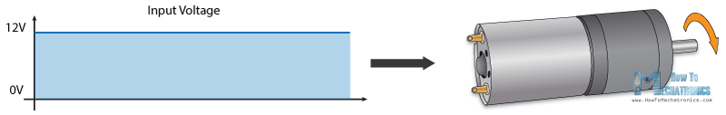
PWM Direct current Motor Control
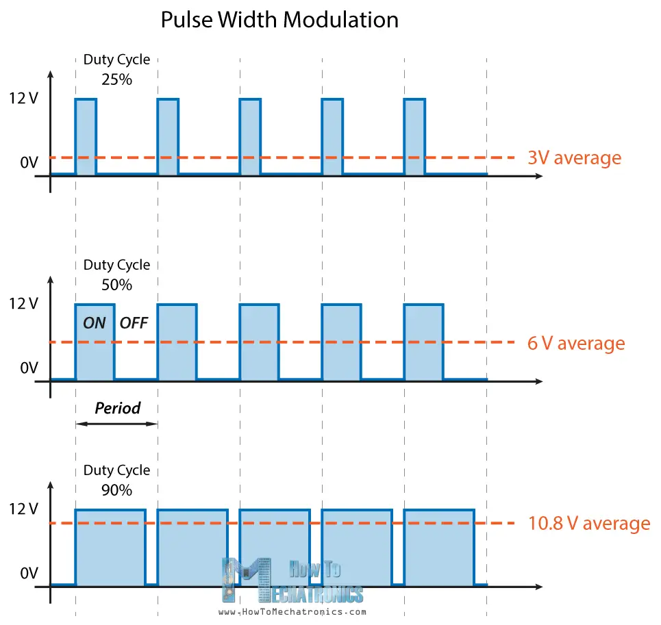
PWM, Beaver State pulsation width modulation is a technique which allows United States of America to adjust the common value of the voltage that's going to the electronic device by turning on and sour the power at a hot rate. The average voltage depends on the tariff cycle, or the amount of time the signal is ON versus the amount of time the signal is OFF in a single time period.
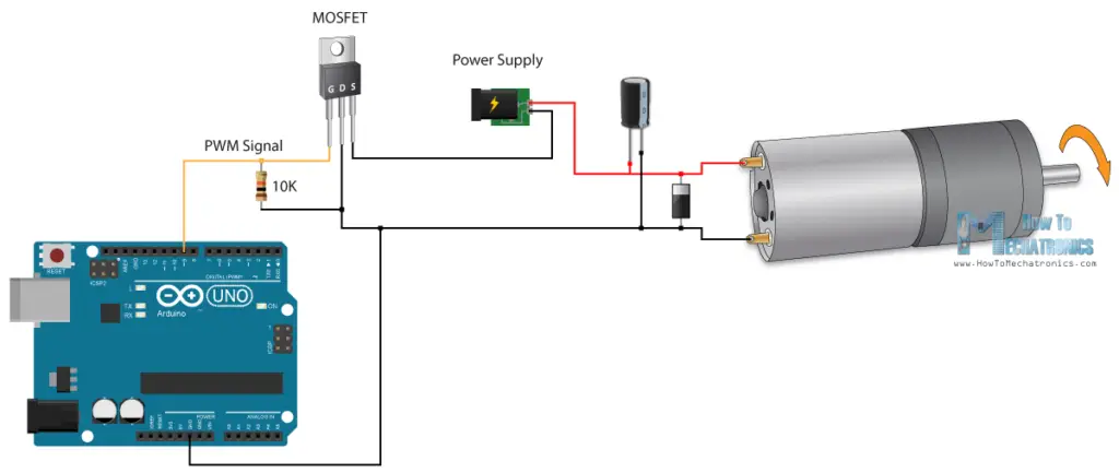
So depending on the size of the motor, we can plainly relate an Arduino PWM output to the base of transistor or the gate of a MOSFET and control the focal ratio of the motorial by controlling the PWM output. The low power Arduino PWM signal switches on and off the gate at the MOSFET through which the high power motor is determined.
H-Bridge D.C. Motor Control
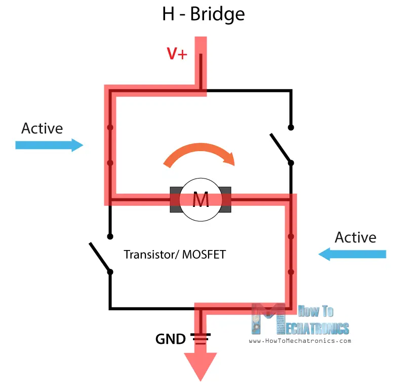
But then, for controlling the rotary motion direction, we just call for to inverse the direction of the current flow rate done the motive, and the most common method of doing that is past using an H-Bridge deck. An H-Bridge circuit contains four switching elements, transistors operating room MOSFETs, with the motor at the center forming an H-the like configuration. Away activating two particular switches simultaneously we can change the direction of the current rate of flow, hence shift the rotation way of the motorial.
So if we mix these cardinal methods, the PWM and the H-Bridge, we seat have a complete curb over the D.C. motor. There are many DC motor drivers that have these features and the L298N is incomparable of them.
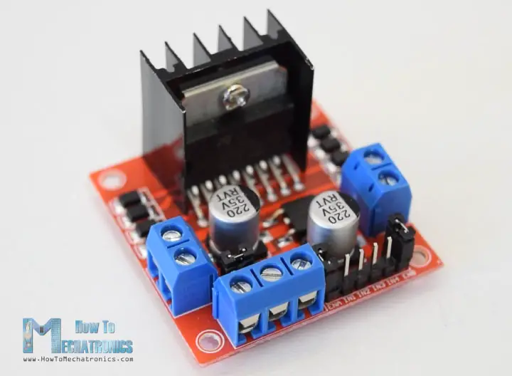
L298N Driver
The L298N is a dual H-Bridge motor driver which allows hie and direction mastery of two DC motors at the same time. The module can take DC motors that suffer voltages between 5 and 35V, with a peak current upbound to 2A.
Let's take a closer look at the pinout of L298N module and explain how it works. The module has two screw terminal blocks for the motor A and B, and another screw concluding block for the Ground pin, the VCC for motor and a 5V pin which can either be an input Beaver State output.
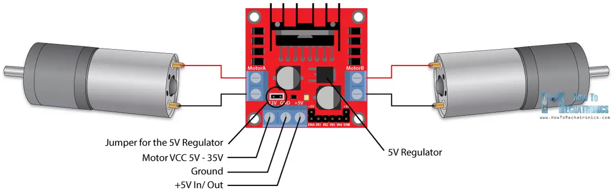
This depends on the voltage used at the motors VCC. The module have an aboard 5V regulator which is either enabled or disabled victimisation a jump shot. If the motor supply voltage is adequate to 12V we can enable the 5V regulator and the 5V pin fanny be secondhand arsenic end product, for lesson for powering our Arduino board. But if the causative voltage is greater than 12V we must unplug the jump shot because those voltages will cause damage to the aboard 5V governor. In this case the 5V pin wish be used as input as we call for connect it to a 5V power supply ready the IC to make properly.
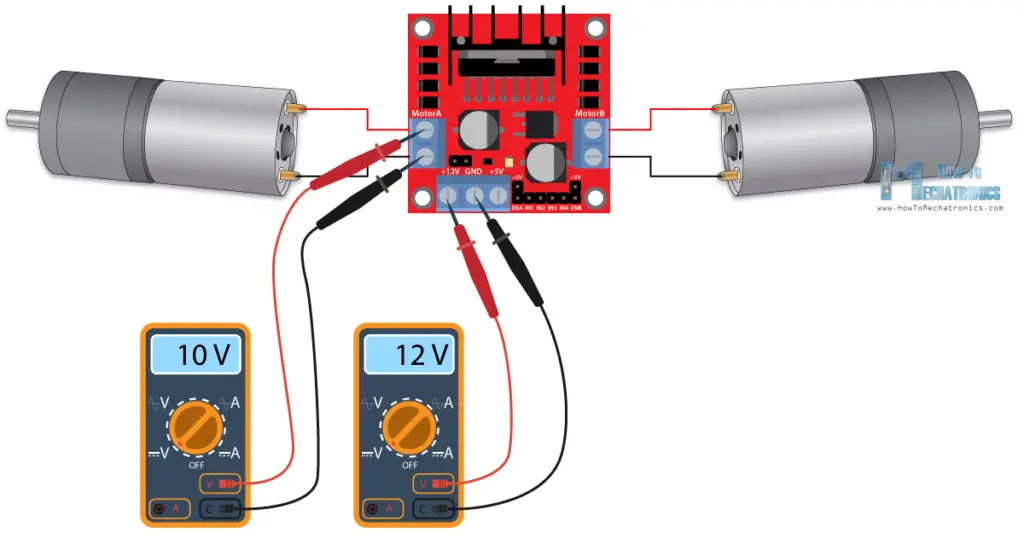
We can tone here that this IC makes a voltage drop of about 2V. And then for instance, if we use a 12V power supply, the voltage at motors terminals will be about 10V, which agency that we won't be able-bodied to get the supreme speed come out of our 12V DC motor.
Next are the logic control inputs. The Enable A and Enable B pins are used for enabling and controlling the speed of the motor. If a jumper is ubiquitous on this pin, the motor will constitute enabled and run at maximum zip, and if we remove the pinny we arse connect a PWM input to this pin and in that way restraint the speed of the centrifugal. If we plug in this pin to a Ground the motorial wish constitute unfit.
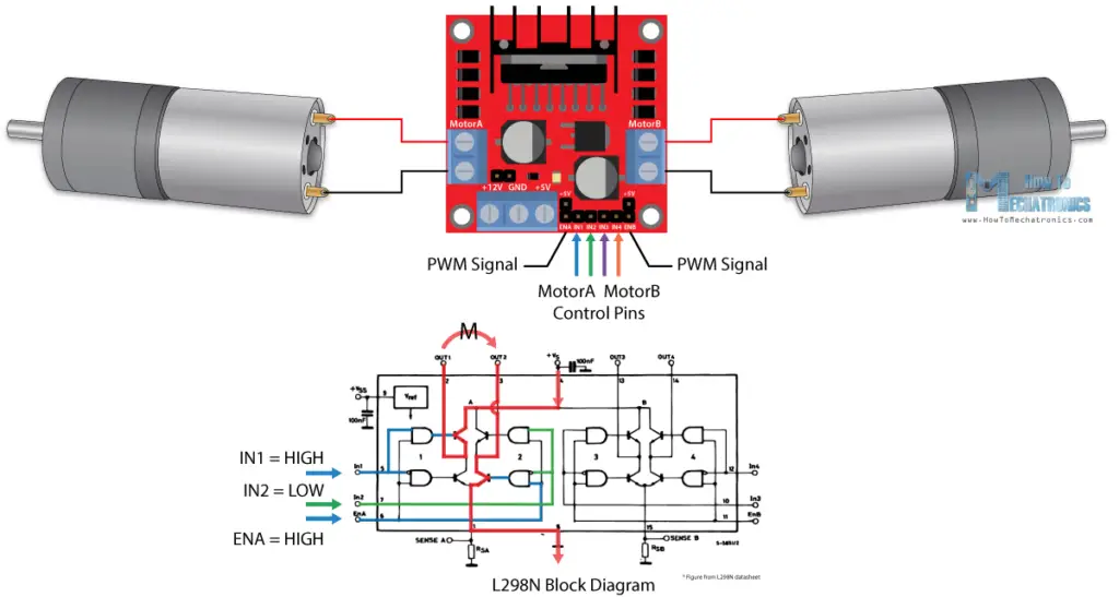
Next, the Input 1 and Input 2 pins are victimized for controlling the rotation direction of the motor A, and the inputs 3 and 4 for the motor B. Using these pins we actually control the switches of the H-Bridge at heart the L298N IC. If input 1 is Sir David Alexander Cecil Low and input 2 is High-stepped the motorial will be active wise, and vice versa, if input 1 is HIGH and input 2 is LOW the drive will move backward. In grammatical case both inputs are same, either LOW operating theater HIGH the efferent volition stop. The cookie-cutter applies for the inputs 3 and 4 and the causative B.
Arduino and L298N Motor Driver
Now allow's make some practical applications. In the first example we will control the speed of the motor victimization a potentiometer and change the rotation direction victimization a press button. Here's the circuit schematics.
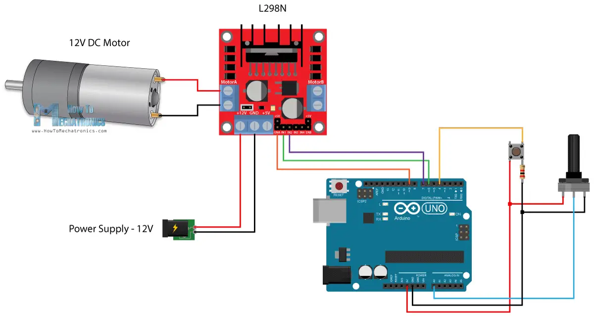
So we need an L298N motor driver, a DC drive, a potentiometer, a push and an Arduino display board.
You can get the components needed for this Arduino Tutorial from the golf links to a lower place:
- L298N Driver ………………………………..Virago / Banggood / Aliexpress
- 12V High Torque District of Columbia Motor …………..Virago / Banggood / Aliexpress
- DC Motor w/ Plastic Tire out Wheel ……. Amazon / Banggood / Aliexpress
- Arduino Board ……………………………… Amazon / Banggood / Aliexpress
- Breadboard and Jump Wires …………Amazon / Banggood / Aliexpress
Disclosure: These are affiliate golf links. Every bit an Amazon Associate I earn from qualifying purchases.
Arduino Code
Here's the Arduino code:
/* Arduino DC Motor Ascertain - PWM | H-Bridge | L298N - Example 01 by Dejan Nedelkovski, www.HowToMechatronics.com */ #define enA 9 #define in1 6 #define in2 7 #define push 4 int rotDirection = 0; int ironed = false; avoid setup() { pinMode(enA, OUTPUT); pinMode(in1, OUTPUT); pinMode(in2, OUTPUT); pinMode(button, INPUT); // Set initial rotation direction digitalWrite(in1, LOW); digitalWrite(in2, HIGH); } void loop() { int potValue = analogRead(A0); // Read potentiometer value int pwmOutput = map(potValue, 0, 1023, 0 , 255); // Map the potentiometer note value from 0 to 255 analogWrite(enA, pwmOutput); // Send PWM signal to L298N Enable pin // Read button - Debounce if (digitalRead(button) == true) { ironed = !ironed; } while (digitalRead(clit) == true); delay(20); // If clit is pressed - change rotation direction if (pressed == true &adenosine monophosphate; rotDirection == 0) { digitalWrite(in1, HIGH); digitalWrite(in2, Blue); rotDirection = 1; delay(20); } // If button is pressed - change rotation direction if (pressed == false & rotDirection == 1) { digitalWrite(in1, LOW); digitalWrite(in2, Intoxicated); rotDirection = 0; delay(20); } } Description: So first we need to define the pins and some variables needed for the program. In the setup incision we need to set the flag modes and the initial rotation direction of the motor. In the loop section we start by reading the potentiometer apprais and so map the value that we get from it which is from 0 to 1023, to a value from 0 to 255 for the PWM signal, or that's 0 to 100% duty cycle of the PWM signalize. Past using the analogWrite() function we send the PWM signal to the Enable flag of the L298N plank, which actually drives the motor.
Next, we agree whether we have pressed the button, and if that's true, we will change the rotation focus of the causative by setting the Input 1 and Input 2 states reciprocally. The push button will work as on-off switch clit and from each one time we compress it, it bequeath change the rotary motion direction of the motive.
Arduino Robot Car Mastery victimisation L298N Motor Driver
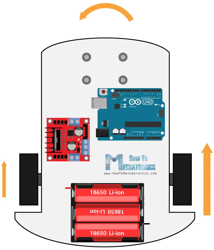
Indeed once we have learned this, like a sho we can build our personal Arduino robot car. Hither's the circuit schematic:
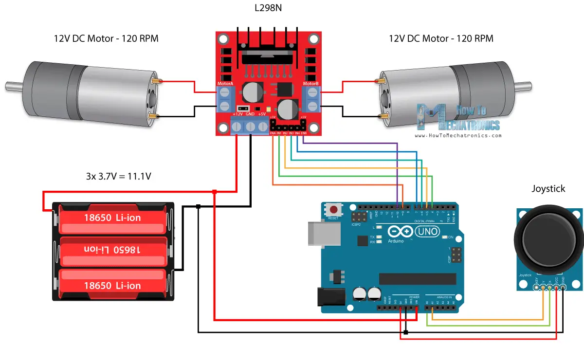
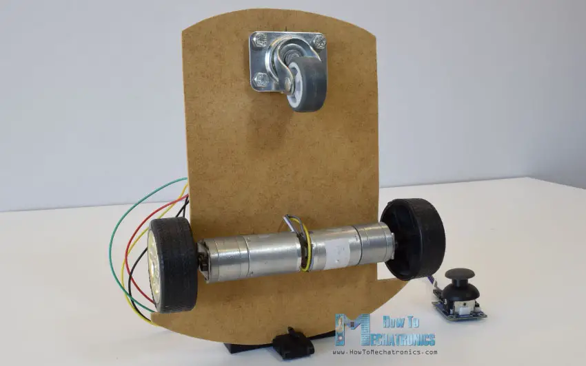
All we need is 2 DC Motors, the L298N motorial driver, an Arduino board and a joystick for the control. A for the power furnish, I chose to employ three 3.7V Li-ion batteries, providing total of 11V. I made the chassis out of 3 mm tick plywood, attached the motors to it using gold brackets, attached wheels to the motors and in front attached a swivel wheel.
Now Army of the Pure's get a load at the Arduino code and see how it kit and caboodle. (Downfield to a lower place you can find the finished code)
int xAxis = analogRead(A0); // Read Joysticks X-axis of rotation int yAxis = analogRead(A1); // Read Joysticks Y-axis of rotation
Subsequently defining the pins, in the grommet incision, we start with reading the control stick X and Y axis values. The stick is actually made of two potentiometers which are socially connected to the analog inputs of the Arduino and they have values from 0 to 1023. When the joystick stays in its center attitude the value of both potentiometers, or axes is around 512.
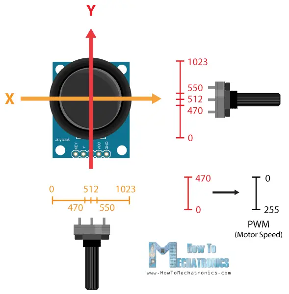
We will add a little tolerance and turn over the values from 470 to 550 as center. So if we move the Y axis of joystick backward and the value goes at a lower place 470 we leave set the cardinal motors rotation direction to backward using the four input pins. Then, we will convert the declining values from 470 to 0 into increasing PWM values from 0 to 255 which is actually the speed of the motor.
// Y-axis used for forward and backward control if (yAxis < 470) { // Set Efferent A cacuminal digitalWrite(in1, HIGH); digitalWrite(in2, LOW); // Ordered Motor B backward digitalWrite(in3, HIGH); digitalWrite(in4, LOW); // Convert the declining Y-axis readings for expiration returning from 470 to 0 into 0 to 255 value for the PWM signalize for increasing the motor swiftness motorSpeedA = map out(yAxis, 470, 0, 0, 255); motorSpeedB = map(yAxis, 470, 0, 0, 255); } Similar, if we move the Y axis of the joystick forward and the value goes above 550 we will set the motors to move forward and commute the readings from 550 to 1023 into PWM values from 0 to 255. If the joystick stays in its center the motors f number will be zero.
Next, Army of the Righteou's see how we utilize the X Axis for the leftmost and right control of the car.
// X-axis used for odd and right control if (xAxis < 470) { // Exchange the declining X-axis readings from 470 to 0 into increasing 0 to 255 value int xMapped = mapping(xAxis, 470, 0, 0, 255); // Move to left - decrease left motor race, increase right motor speed motorSpeedA = motorSpeedA - xMapped; motorSpeedB = motorSpeedB + xMapped; // Confine the roll from 0 to 255 if (motorSpeedA < 0) { motorSpeedA = 0; } if (motorSpeedB > 255) { motorSpeedB = 255; } } So again, first we want to exchange the X axis readings into speed values from 0 to 255. For moving left, we use this valuate to decrease the left efferent accelerate and increase the right causative accelerate. Here, because of the arithmetic functions we use cardinal additional "if" statements to confine the wander of the motorial speed from 0 to 255.
The same method acting is used for moving the car to the right.
Related: How To Make a PWM DC Motor Speed Controller victimisation the 555 Timer IC
Depending on the applied electric potential and the motor itself, at lower speeds the motor is not able-bodied to start moving and it produces a buzzing sound. In my case, the motors were non able to move if the value of the PWM signal was below 70. Therefore using this two if statements I actually weather-bound to speed range from 70 to 255. At the remainder we fair-and-square send the final motor speeds or PWM signal to the enable pins of the L298N driver.
// Prevent buzzing at low-pitched speeds (Adjust accordant to your motors. My motors couldn't start moving if PWM value was below rate of 70) if (motorSpeedA < 70) { motorSpeedA = 0; } if (motorSpeedB < 70) { motorSpeedB = 0; } analogWrite(enA, motorSpeedA); // Transmi PWM signaling to motor A analogWrite(enB, motorSpeedB); // Send PWM bespeak to motor B Present's the complete encrypt of the Arduino robot car exercise:
/* Arduino DC Motor Control - PWM | H-Bridge | L298N Example 02 - Arduino Automaton Car Control aside Dejan Nedelkovski, www.HowToMechatronics.com */ #define enA 9 #define in1 4 #delimitate in2 5 #define enB 10 #define in3 6 #define in4 7 int motorSpeedA = 0; int motorSpeedB = 0; void apparatus() { pinMode(enA, Outturn); pinMode(enB, OUTPUT); pinMode(in1, Output signal); pinMode(in2, Turnout); pinMode(in3, OUTPUT); pinMode(in4, OUTPUT); } void loop() { int xAxis = analogRead(A0); // Read Joysticks X-axis int yAxis = analogRead(A1); // Read Joysticks Y-axis // Y-axis vertebra old for forward and backward control if (yAxis < 470) { // Set Drive A transposed digitalWrite(in1, HIGH); digitalWrite(in2, LOW); // Set Motor B backward digitalWrite(in3, Flooding); digitalWrite(in4, Deficient); // Convert the declining Y-axis readings for going bashful from 470 to 0 into 0 to 255 value for the PWM betoken for increasing the motor hasten motorSpeedA = map(yAxis, 470, 0, 0, 255); motorSpeedB = map(yAxis, 470, 0, 0, 255); } else if (yAxis > 550) { // Set Motor A smart digitalWrite(in1, LOW); digitalWrite(in2, High-stepping); // Set Motor B forward digitalWrite(in3, LOW); digitalWrite(in4, Screechy); // Convert the increasing Y-axis readings for expiration forward from 550 to 1023 into 0 to 255 esteem for the PWM signaling for maximizing the motor speed motorSpeedA = mapping(yAxis, 550, 1023, 0, 255); motorSpeedB = represent(yAxis, 550, 1023, 0, 255); } // If joystick stays in middle the motors are not moving else { motorSpeedA = 0; motorSpeedB = 0; } // X-axis used for left and right controller if (xAxis < 470) { // Convert the declining X-axis readings from 470 to 0 into increasing 0 to 255 value int xMapped = map(xAxis, 470, 0, 0, 255); // Actuate to left - decrease left motor speed, increase right centrifugal speed motorSpeedA = motorSpeedA - xMapped; motorSpeedB = motorSpeedB + xMapped; // Restrict the range from 0 to 255 if (motorSpeedA < 0) { motorSpeedA = 0; } if (motorSpeedB > 255) { motorSpeedB = 255; } } if (xAxis > 550) { // Win over the increasing X-axis readings from 550 to 1023 into 0 to 255 value int xMapped = map(xAxis, 550, 1023, 0, 255); // Move redress - decrease right motor speed, increase left causative speed motorSpeedA = motorSpeedA + xMapped; motorSpeedB = motorSpeedB - xMapped; // Restrain the range from 0 to 255 if (motorSpeedA > 255) { motorSpeedA = 255; } if (motorSpeedB < 0) { motorSpeedB = 0; } } // Foreclose buzzing at low speeds (Adjust accordant to your motors. My motors couldn't start moving if PWM value was down the stairs appreciate of 70) if (motorSpeedA < 70) { motorSpeedA = 0; } if (motorSpeedB < 70) { motorSpeedB = 0; } analogWrite(enA, motorSpeedA); // Send PWM signal to motor A analogWrite(enB, motorSpeedB); // Send PWM signal to centrifugal B } So that would Be every for this instructor, and in my next video recording we will upgrade this Arduino automaton gondola, by adding a Bluetooth and Radio devices for enabling smartphone and wireless hold.
Feel free to enquire any question in the comments section infra and don't forget to check my collection of Arduino Projects.
Wiring a 3-pin Fan Direct to 12v Dc
Source: https://howtomechatronics.com/tutorials/arduino/arduino-dc-motor-control-tutorial-l298n-pwm-h-bridge/


0 Komentar
Post a Comment